Interactive Computer
How a computer works
Camboard Technology
Computer science software for k12 and ks3 computing curriculum..
Key Features
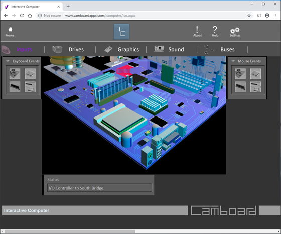
See how the inside of a PC works
App runs in a web browser works on a windows PC, apple Macintosh, iPad, chromebook and tablet computers.
App requires an internet connection to use it.
No software to install and maintain.
Interactive Computer simulates the main processes of a working PC.
The app is a great introduction to the inner workings of a computer.
The 3D realistic parts of a computers motherboard, sound card, AGP card, hard disk drive and cd/dvd drive are all simulated.
Students can see what is going on inside a computer. The computers main systems are simulated.
Interactive Computer is a powerful simulation of the main processes involved in running applications and using hardware on a Windows Personal Computer.
Great for use with computer science and computing curriculum.
Interactive Computer simulates these events...
Events
Mouse events
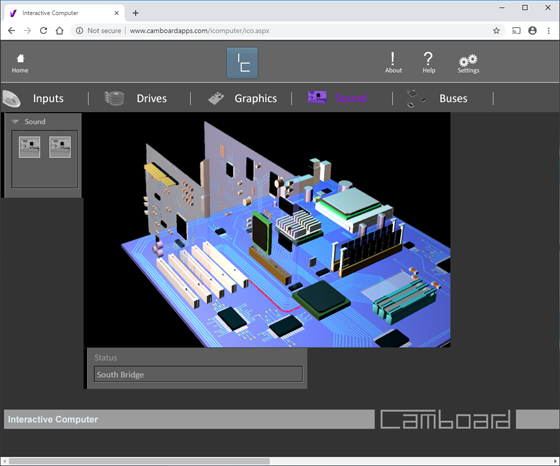
Simulates data travelling from the mouse port to the i/o controller then to south bridge.
Data then travels to the north bridge and onto the CPU. From the CPU the mouse data is transferred back to the north bridge and into a memory location on the AGP card.
When the data leaves the CPU it will update the graphics card with a new pointer position or menu opened etc.
Keyboard events
Simulates data travelling from the Keyboard port to the i/o controller then to south bridge.
Data then travels to the north bridge and onto the CPU.
From the CPU the Keyboard data is transferred back to the north bridge and into a memory location on the AGP card.
When the data leaves the CPU it will update the graphics card with a new text cursor position etc.
Hard Disk events
(Read to Memory) simulates data being read from the hard drive to memory.
The arms on the hard disk move across the platters to read data from a specific location.
Data is then transferred to the hard disk controller which sits under the platters.
A ribbon cable (not shown) connects the controller to the IDE slot on the motherboard.
Data moves through the IDE slot to the south bridge. .
Data then travels to the north bridge and onto the CPU. Data is transferred to memory from the CPU.
(Write from Memory) simulates data being written onto the hard drive from memory.
Data is read from memory into the CPU. Data leaves the CPU and travels to the north bridge.
From here the data travels to the south bridge. Data is then routed to the IDE connectors.
Data is received onto the disk controller and then transferred to the write heads on the arms of the hard disk.
The arms on the hard disk move across the platters to write data to a specific location
Virtual computer
Sound Card Events
Sound Card (Microphone) Simulates analogue data from a microphone converted to digital data.
Analogue data is inputted into the sound card through a socket.
An analogue to digital converter (ADC) converts the signal into digital data.
The sound card moves this data through the PCI connector onto the PCI bus.
The data travels to the south bridge. Data then travels to the north bridge and onto the CPU.
Sound Card (Loudspeakers) Simulates digital data being converted into an analogue signal which is fed to the speaker sockets on the sound card.
Data leaves the CPU to the north bridge and travels to the south bridge.
Data is routed to the PCI bus. The PCI socket connects the sound card to the PCI bus.
Data is transferred from the PCI bus to the sound card.
GPU
Ports
CPU to LAN
Data travels from CPU to LAN port on GPU.
CPU to Audio
Digital data is processed by the CPU it travels to the Audio port where it’s converted into an analogue signal.
CSI to CPU
Data is transferred from the CSI port to CPU.
CPU to DSI
Digital data is processed by the CPU it travels to the DSI port. The DSI port is typically used for driving small screens like a LCD.
CPU to GPIO
Digital data is processed by the CPU it travels to the GPIO port.
In reality data travels in both directions depending on whether an input or output device are connected through an external buffer board to the GPIO connector.
CPU to SPI
Digital data is processed by the CPU it travels to the SPI port. This port is part of the GPIO.
CPU to UART
Digital data is processed by the CPU it travels to the UART port. This port is part of the GPIO.
CPU to I2C
Digital data is processed by the CPU it travels to the I2C port. This port is part of the GPIO.
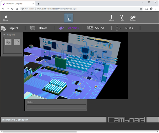
Graphics & Memory
CPU to Graphics
Digital data is processed by the CPU it travels to the Graphics port where OpenGL graphics are supported. The data is processed and converted into a graphics stream.
CPU to RCA
Digital data is processed by the CPU it travels to the Graphics port where it’s converted into a PAL stream ready to be transferred to the RCA socket.
CPU to HDMI
Digital data is processed by the CPU it travels to the Graphics port where it’s converted into a HDMI data format ready to be transferred to the HDMI socket.
CPU to SDIO
The SDIO port connects the CPU to a memory card that slots into the SD connector on the underside of the Pi. Data is transferred from the CPU to the SDIO port in the GPU.
CPU to Memory
Data is transferred from the CPU to the Memory port in the GPU
LAN
Ethernet (Data Out)
Data is processed by the CPU it travels to the LAN port. From here data travels through the pcb to the LAN chip. The LAN chip processes data and sends it to the Ethernet socket on the edge of the circuit board.
Ethernet (Data In)
Data is received at the Ethernet socket. Data moves to the LAN chip where it's processed. Data is moved through the circuit board to the LAN port on the GPU. Data is moved through the GPU bus into the CPU.
USB Typically used for connecting a mouse and keyboard and other external devices to the pi.
USB (Data Out)
Data is processed by the CPU it travels to the LAN port. From here data travels through the pcb to the LAN chip. The LAN chip processes data and sends it to the USB socket on the edge of the circuit board.
USB (Data In)
Data is received at the USB socket. Data moves to the LAN chip where it's processed. Data is moved through the circuit board to the LAN port on the GPU. Data is moved through the GPU bus into the CPU.
Graphics
CPU to RCA
Digital data is processed by the CPU it travels to the Graphics RCA port where it’s converted into a video signal.
CPU to HDMI
Digital data is processed by the CPU it travels to the Graphics HDMI port where it’s converted into a video signal.
CPU to RCA socket
Digital data is processed by the CPU it travels to the Graphics RCA port where it’s converted into a video signal. Data is then routed to the RCA socket.
CPU to HDMI Socket
Digital data is processed by the CPU it travels to the Graphics HDMI port where it’s converted into a video signal. Data is then routed to the HDMI socket.
Ports
Audio
CPU to Audio
Digital data is processed by the CPU it travels to the Audio port where it’s converted into an analogue signal.
CPU to Audio Socket
Simulates digital data being converted into an analogue signal which is fed to the audio socket.
CSI DSI
CSI Connector to CPU
Data is transferred from the CSI port to CPU. The CSI port is used for connecting a digital camera.
CPU to DSI Connector
Digital data is processed by the CPU it travels to the DSI port. The DSI port is typically used for driving small screens like a LCD.
GPIO
The GPIO input/output pins are situated on the top left hand side of the circuit board. These enable input output devices to communicate with the pi.
CPU to I2C Connector
Transfers data between the I2C connectors on the GPIO to the CPU.
CPU to SPI Connector
Transfers data between the SPI connectors on the GPIO to the CPU.
CPU to UART Connector
Transfers data between the UART connectors on the GPIO to the CPU.
System Requirements
Requires an internet connection and web browser
Runs on a P.C, Mac, Tablet and SmartPhone
Try Now
Try 14 day trial now...